I had no idea if the fuel pump worked or not so decided to take it apart and see what needed to be replaced.

Looks in a bad way initially.

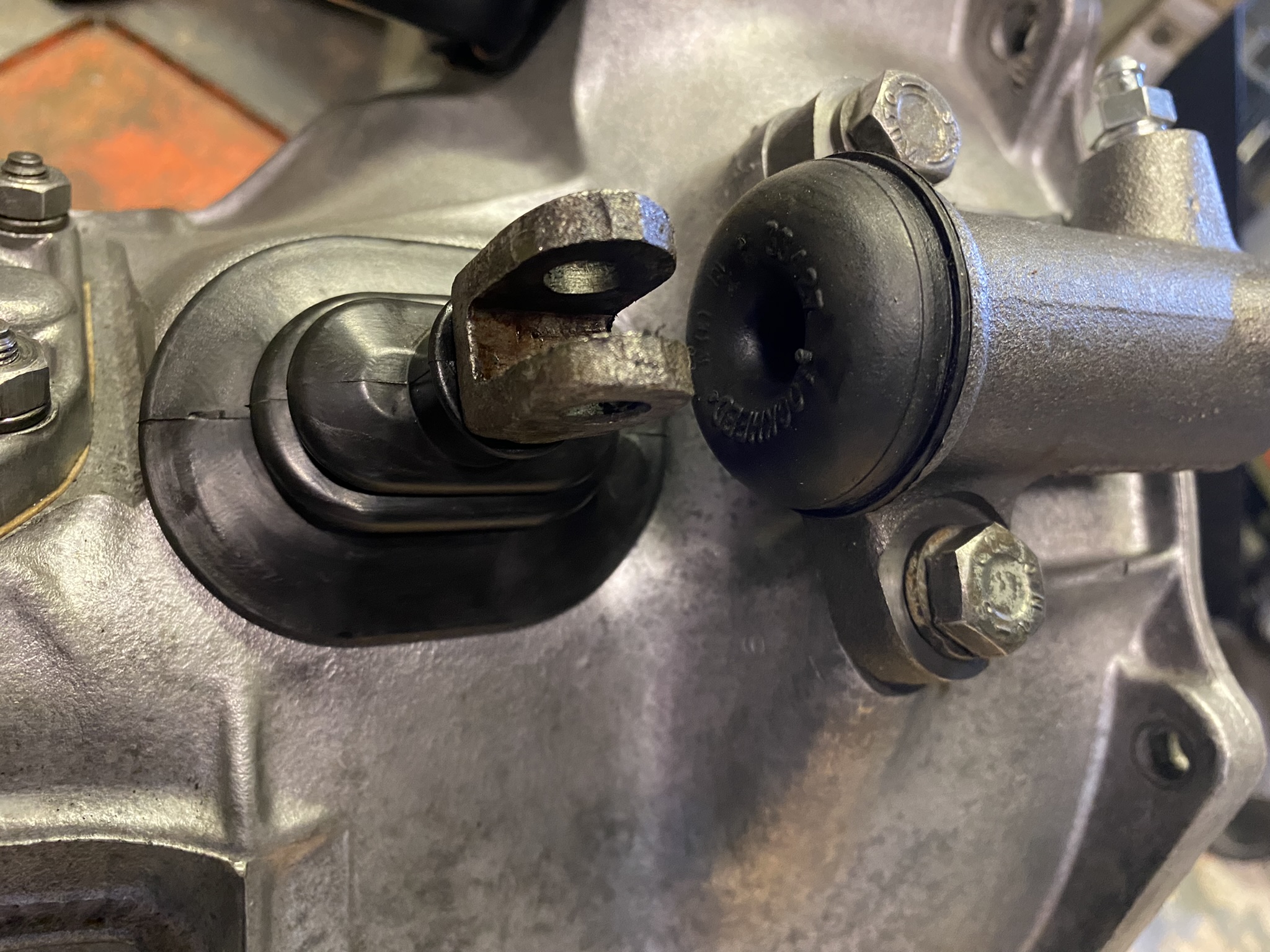
The pipes have had it.


The bracket should easily clean up with my trusty wire wheel.


Need to remove the plate that hold the two banjo unions in place, as I believe they are called. I'd call them nozzles. One for inlet and one for outlet.

I think they will clean up ok. Can see any signs of cracking.

I am aware that the rubber that surrounds the values get brittle and hard and can crack, so new values definitely required, even though when I tested the actual valves they seemed to work fine.

You have to undo the screws to get access to the diaphragm.

It is interesting to see the diaphragm as there is a plastic cover with SU stamped on it. In all the photo's I've seen for replacement diaphragms they don't have this plastic cover.
The gasket on the top cover needs replacing.

To be able to check the diaphragm you only need to unscrew it. The diaphragm is connected to the points mechanism.

This reveals the spring. The rubber on the diaphragm is in really good condition, so will give it a good clean and see how we get on.

Time to look at the electronics end. only the one screw holding this down.


Then remove the rubber washer off the thread.

and remove the nut.

This exposes the earth cable and live.

By removing the screw that holds down the live wire you can get to the points.

There's a bit of wear on the points connections so I think I'll replace the points as well.


And that's it all dissembled. Now to order new parts and rebuild!

Apart from replacing the points I did nothing more two the bottom section of the fuel pump other than put it back together.
I wanted to make sure the edges were really clean before inserting the new values. There was lots of bit of old hard rubber that could result in a leak.

Once I was happy I fitted both the value and rubber seal. Obviously you need to make sure you have these the right way round as each value only works one way.


The inlet valve does have a gauze filter to stop any rubbish getting into the fuel pump or carbs.

Requires another rubber seal.

You need to make sure these nozzles sit correctly whilst screwing on the retaining plate.


Next is the most complicated part, which is setting the diaphragm correctly.
It is easy to screw this back into the points but there is a guide which you need to follow.

With the cover off so you can see the points and the diaphragm screwed in you should be able to push the diaphragm into the housing and the points will move up and down.
When you push it should drop and hit the housing.

And return when you let go. This is what the magnetic coil will do when working properly.

You start by screwing in the diaphragm until the points stop flipping over. Then you need to unscrew the diaphragm up to the moment that the points start to flip over and start working each and every time. You should then unscrew the diaphragm to the left the nearest hole that where it successfully flips over.
When you get to this point you need to undo the diaphragm by a further 4 holes.

And that should be it for the set up.
However here's a video that I found very helpful: SU Fuel Pump Rebuild
Now that the diaphragm is all set correctly, you can fit the gasket and bolt the 6 screws back on to bring it all together.

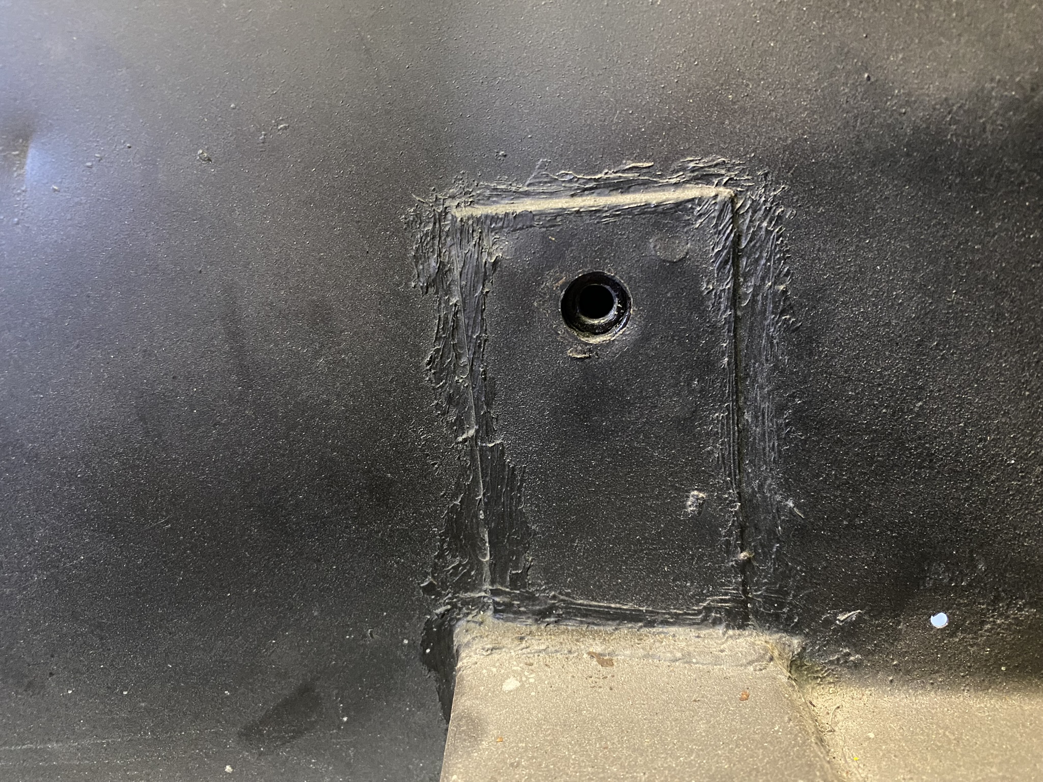
I spray painted the housing with black chassis paint and pushed on the seal.

Then you slide on the rubber bracket support and fit the earth wire.

It was at this point that I wanted to test the pump to see if it worked. It is really easy to do if you have a battery or battery charger. You connect the red positive clip to the earth cable and the black negative clip to the live connector on the bottom of the pump and turn on the power!

This is what happened. (Turn on your sound)
Success!! This is what a fuel pump should sound like when there is no fuel to pump. It continuously pumps and makes way more noise then when it is pumping fuel.
Also there was plenty of air being pumped in and out of the nozzles so I was confident it would work with the fuel.
Next up you have to prepare the pump to be fitted to the chassis and that means making sure the outlet half of the whole pump is at the top regardless of where the nozzle ends up pointing.

Once you've got that then you can fit the pump to the bracket ready for fitting.

I've covered fitting the fuel pump in this post: Fuel System Fitting