Since getting the engine back from the specialists there have been many weeks where I have made some progress and other weeks where I have been left frustrated. Progress has not been where I wanted it to be. But that is life.
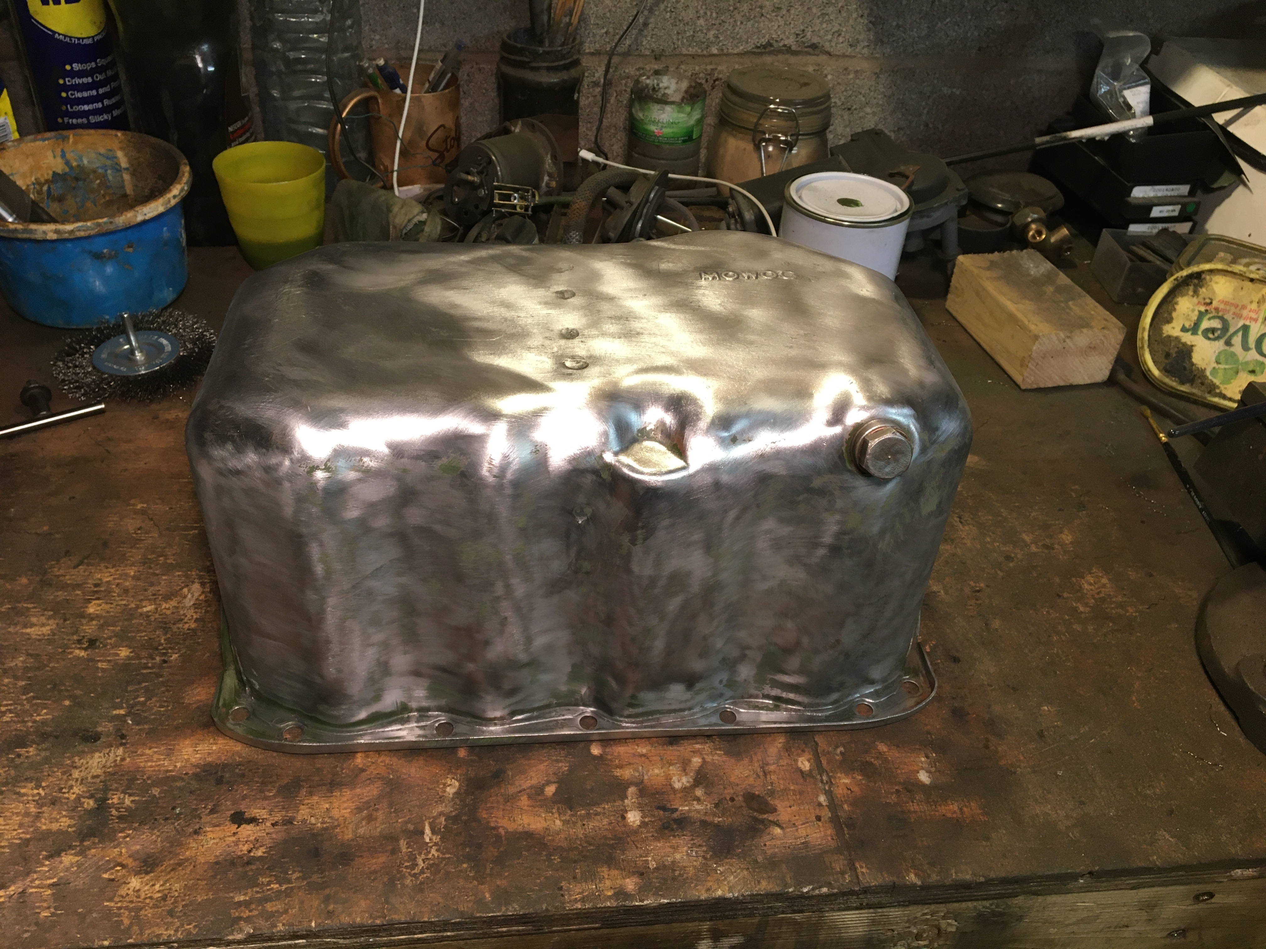
First thing was to paint it, which also meant removing any old paint and degreasing all the parts in preparation for the new paint.


The engine stand made painting much easier and was very pleased with the results.


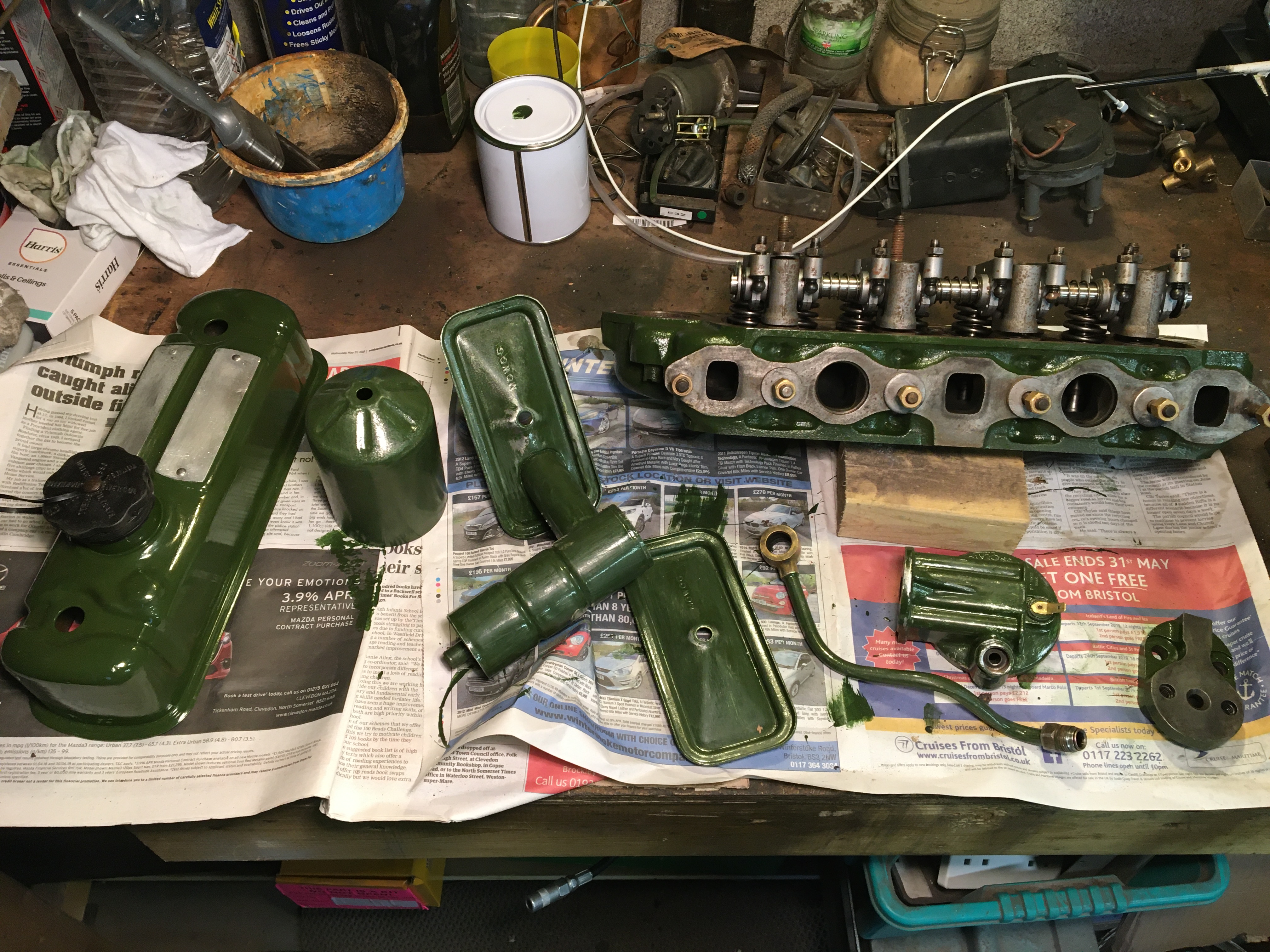
Next up was the exterior components and the head.
Time to rebuild!
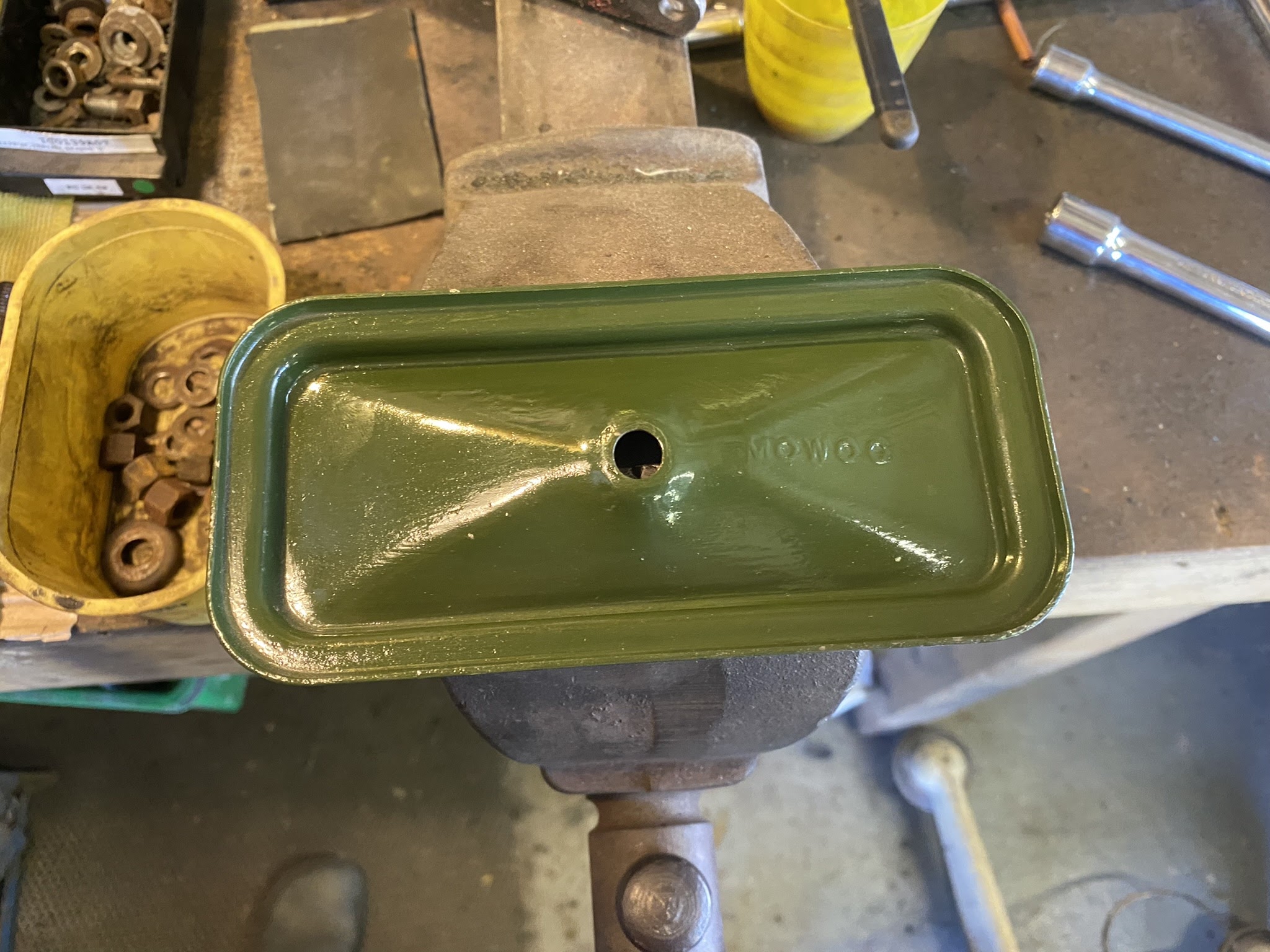
I figured it would be best to get the sump on and then I could get it on my bench to carry on with the rebuild there. That meant attaching the sump filter pipe.
I should make it clear that you must make sure all surfaces are very clean and are thoroughly degreased, otherwise you may be prone to oil leaks.


Not very challenging only three anchor points.

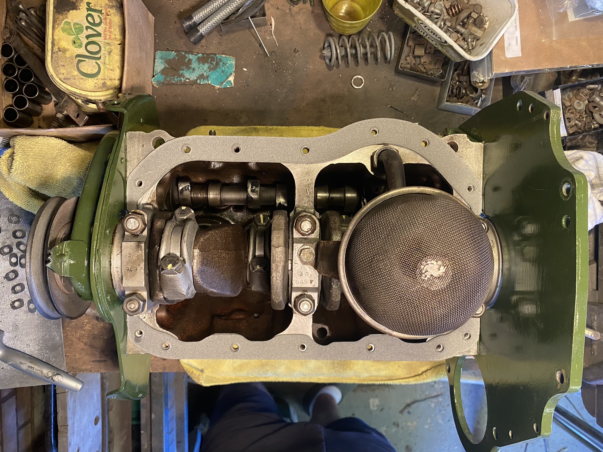
You can see my repair on the bottom of the filter that had a hole in it that I very carefully welded up. Wasn't easy as the wire mesh was very fine and melted into nothing. So had to weld at distance to reduce the current. Did the job and no one is going to see it for a while hopefully.

Fitting the sump! In the gasket kit it came with cork gaskets for the two ends. You must make sure there is no left over old gasket in the slots. The cork gaskets need to be trimmed so that they stick out just a little over the level of the sump flange. Haynes manual says 1.5mm , but I read that there is no harm being a little over. You just can be under that as the cork won't compress properly and you'll get oil leaks.


I left it at about 1.8mm, guess we'll find out in time if that was ok, but when I tightened up the sump if left nice and tight.

Then I test fitted the main gaskets.


However reading on the MG Midget forums it does recommend that you apply a small amount of blue gasket compound where the cork gasket meets the main ones.


Then you can push the gasket into the blue compound...

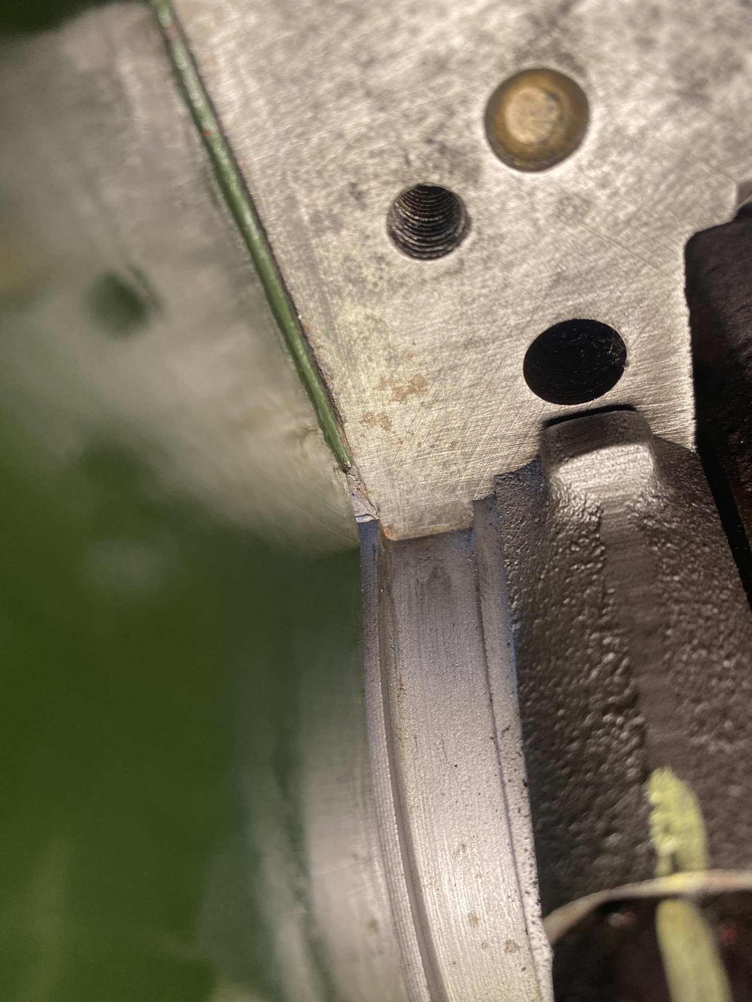
And then fit the sump. You need to make sure the gasket lines up and you can see all the holes.

The gap here below is caused by the cork gaskets which is supposed to happen.

Then you can start to finger tighten the bolts slowly.


Once all finger tight you can start to tighten up the bolts with a torque wrench as it is very easy to tread the bolts by over tightening them. Haynes manual recommends 6 lb f ft, which isn't very much at all.

You should see some of the blue compound push out.

Now ready for the next stage, which was to insert the cam followers.

Need to make sure the guides are clean and the cam followers are as well.


You need to coat them in engine oil and then insert them into the guide.


I used my finger to slide them up and down to make sure all surfaces were covered in oil.


I don't know why but I got a little buzz when I turned over the crank and saw the cam followers rise and fall one by one.

Now you don't normally need to fit the push rods now, that should happen when you have fitted the head. But I want to see what they looked like and also thought it was the safest place for them during the rebuild. Still need to cover them in oil before fitting into the cam followers.


Next you can fit the two covers.

The gasket was quite fiddly as it didn't really want to stay on the lip of the cover. But once in place it does stay there.

I don't know why but the right hand cover has a rubber seal and the left cover a fibre washer on the 1098 engine.

The oil breather cover is no different in fitting.


All done, now round the other side for the oil filter.

Before you can attached the oil filter you need to attach the adaptor and the head that the filter bolts on to, making sure the gaskets are in place.


Then you can fit the connecting pipe.


I bought a new paper filter type of oil filter and a few new spares.

First put the rubber o ring on the main bolt and fit the bolt into the filter bowl.

Then goes the spring

Then washer

Then felt washer

then the plate

Then the filter

On the mounting head you need to fit the seal before mounting the bowl and tightening the bolt.


Next I fitted the dip stick tube, which did take a good few taps to get it to properly sit down all the way.

I then fitted my new tap. I broke my old one moving the engine once, but it was also totally clogged up.
As was the hole from where the tap goes into the water chamber around the cylinders. To unblock this hole I used a small philips screwdriver and tapped it with a hammer. The hole is on a slope down to the tap, but it is straight and with a little force eventually broke through all the gunk and rust that had blocked it up.


Nice bit of bling!

Now to fit the fly wheel. All the surfaces must be clean and degreased.

Turn the engine until pistons 1 and 4 are Top Dead Centre (TDC) and then find the 1/4 mark on the fly wheel and make sure that goes to the top.


You can then fit the wheel locking nuts and brace the crank and set the torque wrench to 40 lb f ft.


Now for me at this stage disaster struck, my locking tabs were shot! You should replace them each time which normally wouldn't be a problem. But you cannot buy new locking tabs for a 1098 10cc engine for some reason. The ones for the 948 are smaller, as I found out.


So the only option was to use blue Loctite 243 instead.

This meant I had to tighten up all the bolts without any Loctite on them and then clean both the holes and bolts really, really well. There cannot be any grease.


Once all cleaned you then tighten up all four bolts and remove one bolt at a time and apply the thread lock and then tighten up the correct torque setting of 40 lb f ft.

You don't need to cover the whole bolt, just the end as when you tighten it the liquid will spread to the rest of the bolt where it meets the thread in the hole, so it only goes where it is needed.


It is really important to make sure the fly wheel face is spotlessly clean and thoroughly degreased in preparation for the clutch. You can make out a faint ring on the face of my fly wheel which was where the prior owner had let the clutch plate wear down too much and the bolts in the plate made a very, and thankfully shallow groove. Not enough to need replacing.
The clutch cover was very dirty and covered in grease and grime, not what you want anywhere near your clutch or freshly painted engine.


Again you can see the shallow groove in the cover ring caused by the worn plate.
Nice new clutch plate ready for fitting. In the Haynes manual it says to find the wording on the plate that says "Fly Wheel Side"
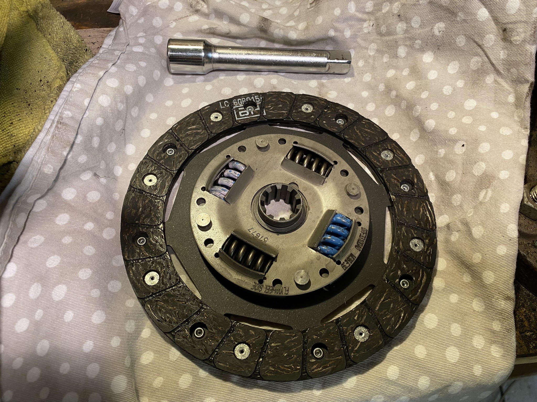
And there is was. Trouble was they have clearly printed this on the wrong side as it wouldn't sit correctly against the fly wheel that way round. It kept knocking on the fly wheel bolts. So make sure you check first.


You can buy a clutch alignment tool to make sure the plate sits exactly in the middle whilst you fit the clutch cover. However if you have a socket set you might be lucky like me and have an extender that fits into the hole at the centre of the fly wheel perfectly.
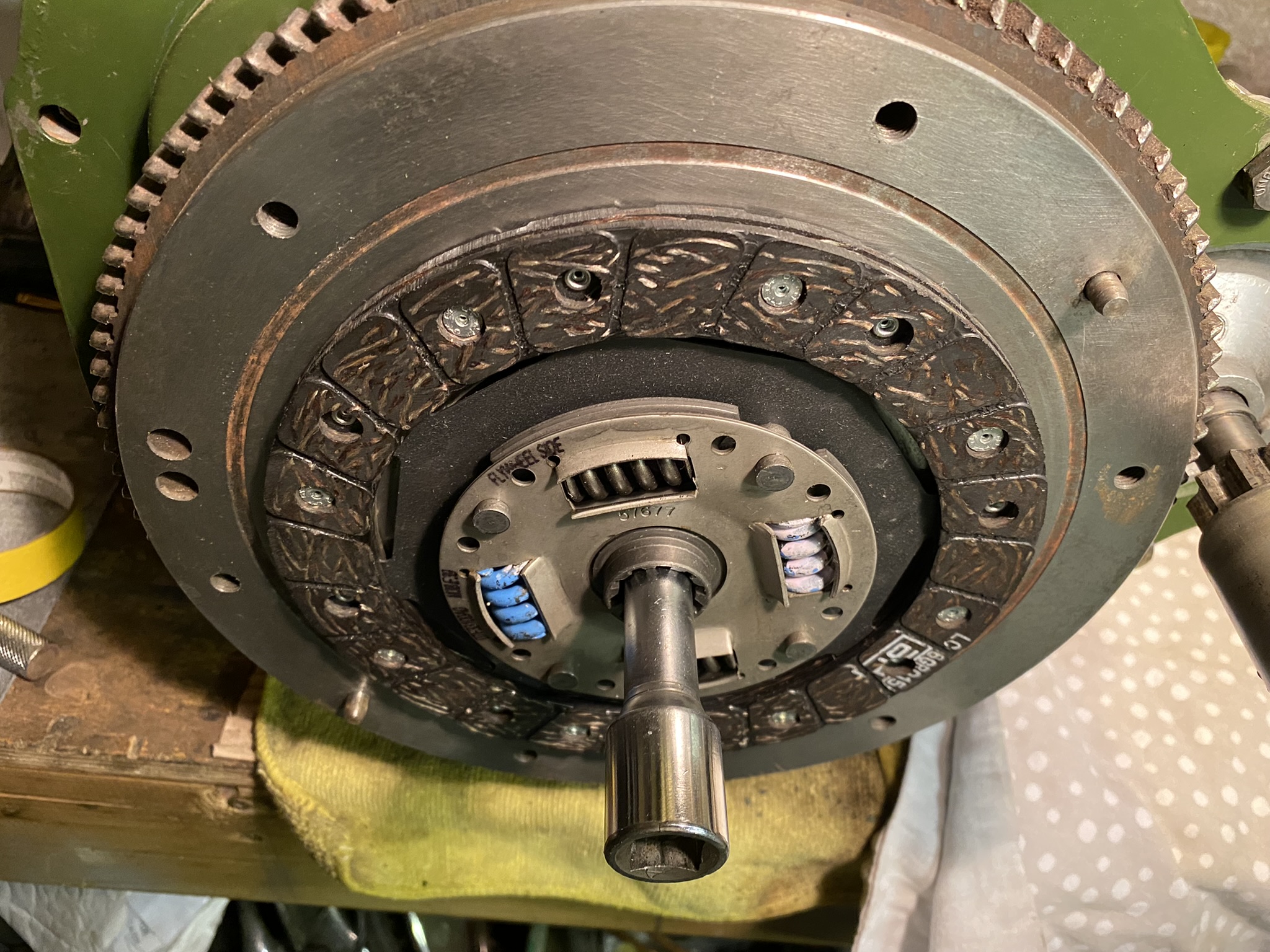

Although it fitted into the fly wheel very well the plate wasn't so tight, for this you can wrap some tape around the shaft until the plate slides on nice and tight.


Then slot into the hole on the fly wheel and offer up the clutch cover.

The cover came up really well.


Holding on to the cover tighten up one bolt at a time finger tight. When all in place you need to make sure at this point that the plate is perfectly in the centre. If not you won't be able to fit the gearbox on properly.

Then start to tighten each bolt working on opposite sides so that the cover presses against the plate evenly until all the bolts are all tight.

When you are happy all the bolts are tight you can remove the alignment tool and you should see that the slot for the main shaft is dead centre.

I made the decision to fit the head whilst the block was in the car. I wanted to make sure I had the correct torque on the bolts and felt the best place to do that was with it in the car. So next was to attached the gearbox that had recently come back from Bristol Transmissions, who did a complete overhaul. Turned out the only things needing replacing was the bearings, shims and the lay gear.
I also replaced all the rubber engine and gearbox mountings as they had all perished.
Good to know it has many miles left.

If you've lined up the clutch plate properly the gearbox should slide right on it and then you tighten up the 8 bolts. There is the exhaust bracket that needs to go on the bottom two bolts and you need to bolt on the earthing point, but I'll cover that in another post.
It is also recommended that you fit the starter motor at this point as it is very difficult once the engine and gearbox is in the car.


Now I've just got to pick it up and pop it into the car! My friend kindly lent me his engine hoist which made the job much easier. Make sure you remove the gear leaver beforehand.

Whether you are using ropes or straps you need to get the engine and gearbox pointing down and away from you. You need a decent angle so that when you raise the engine the end of the gearbox is point down towards the transmission tunnel. It took me a couple of goes and adjustments before I got it right.

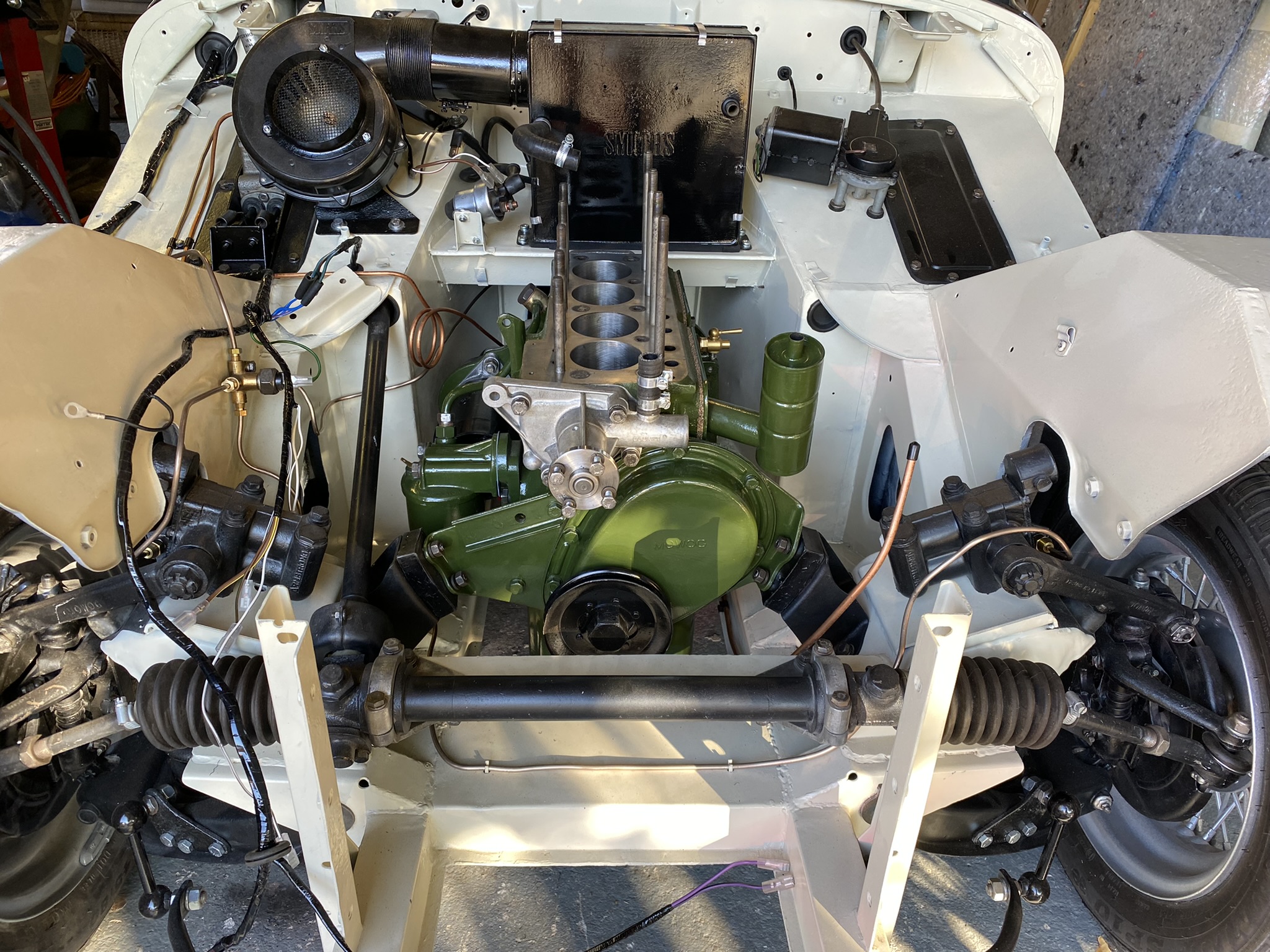
But once I had it point at the right angle it slotted in without much fuss. Just have to take it slow and push it in a little, then drop it down a little and repeat until your home.

To see this engine back in the car after nine years I got quite emotional.

Especially when it looked like this all that time ago

I'm very happy!