Monday 9 January 2023

Fitting the Driveshaft

Once the engine and gearbox is in place it is time to fit the driveshaft.

If you have the equipment or know someone who has you can check if your driveshaft is balanced correctly. This will reduce vibrations and increased wear on the universal joints.


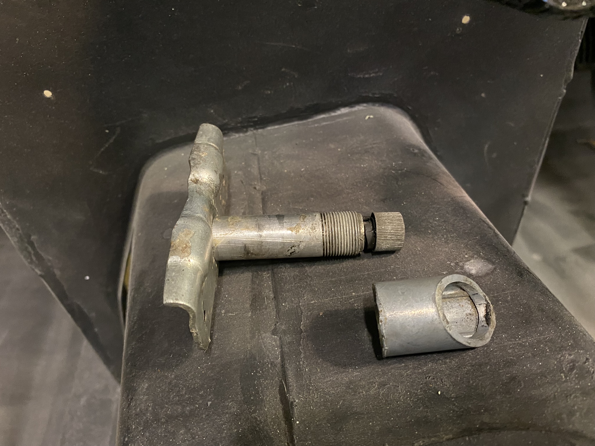
There are four other parts to check before refitting the driveshaft and they are the two universal joints which must have no unwanted movement at all. If you hold the main shaft in one hand and either end in the other shouldn't feel anything other then the direction you are moving. Try twisting it backwards and forwards and around to see if there is any play. 

Fortunately mine seem good for now.

The next thing is the teeth the slide onto the main shaft of the gearbox. There should be no wear on this at all. 


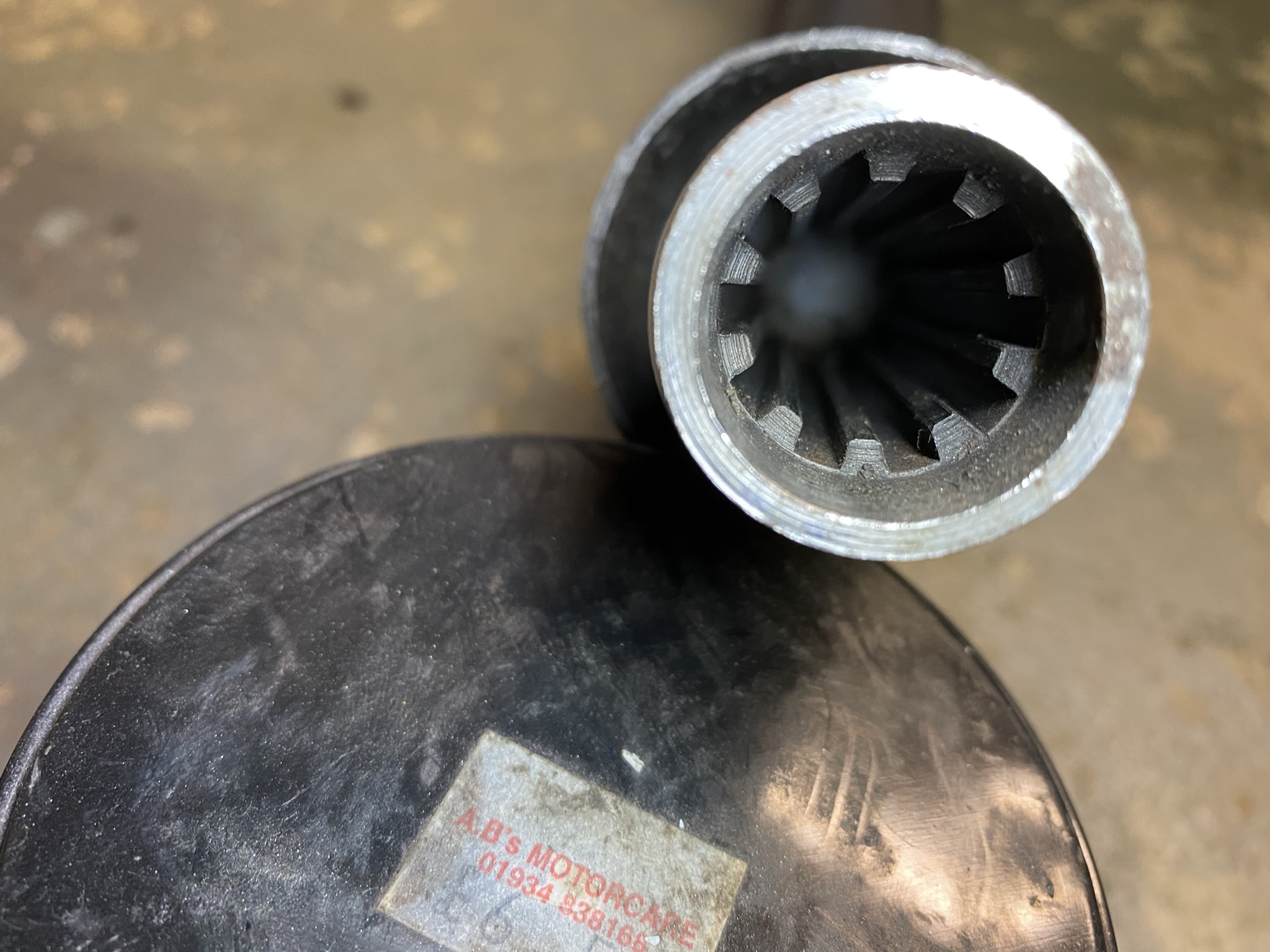
A small amount of grease is recommended before attempting to fit, as there no option in the transmission tunnel.


Then you should check the face of the axle end to ensure it is clean and smooth.


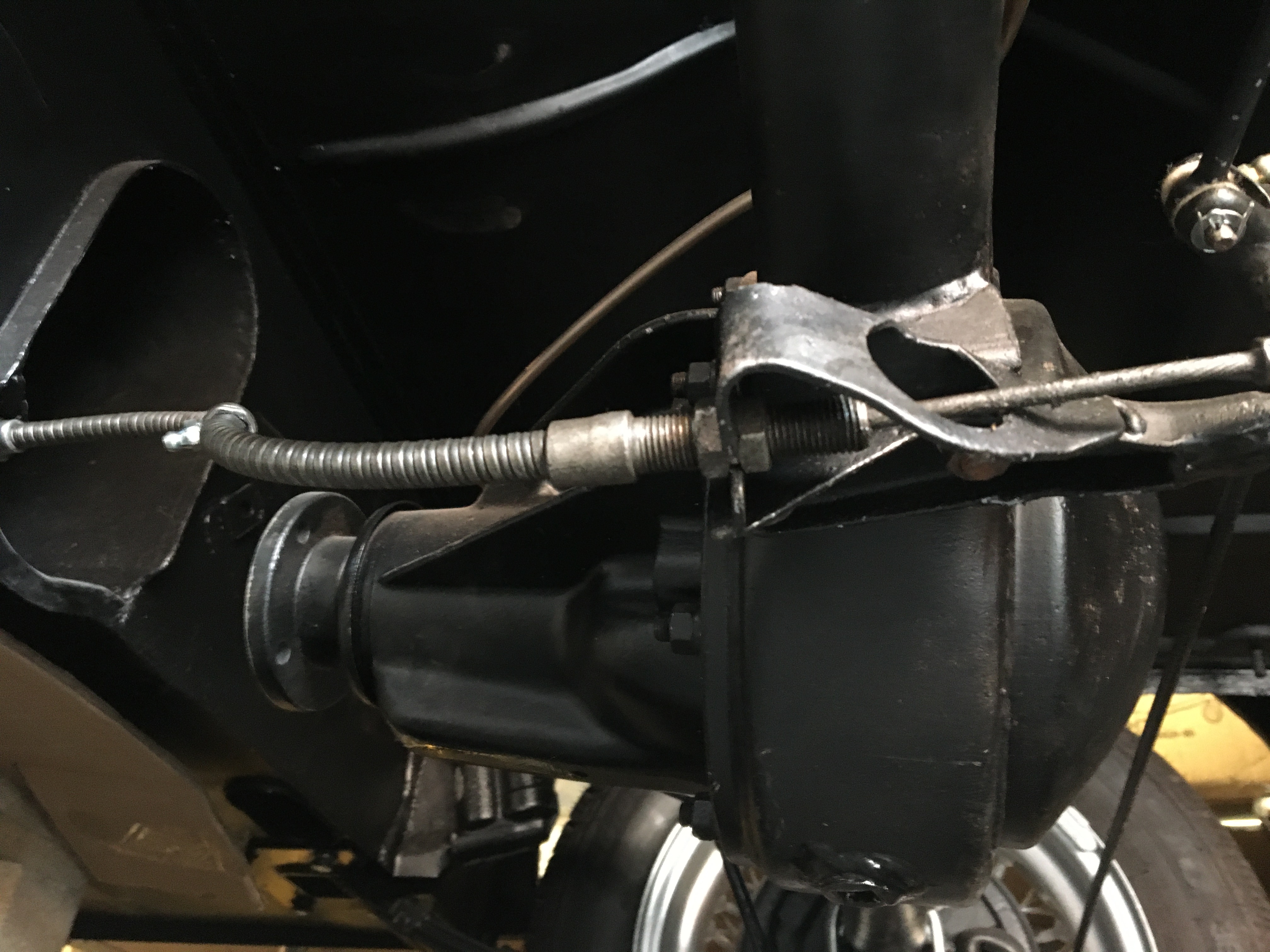
If your fuel tank is in position the best way to move the driveshaft into position is to slide it down the left hand side of the tank and over the axle.


You will then find that it is challenging to slide the driveshaft down the tunnel and on to the gearbox. The reason being is that because of the universal joint the end of the driveshaft points downwards and it needs to be level.

Some lucky people will have access holes cut into the underside of their chassis. The only one I had was the handbrake mounting point. Which meant I had to use a length of wood to lift the end of the driveshaft whilst pushing it on to the gearbox. All the time not really being able to see what I was doing. It took a while!


With the driveshaft finally attached to the gearbox I could then tighten the bolts to link the driveshaft to the axle.


Once that was all done I suddenly realised the car could technically move by itself. Once I had got the engine running that is!

Handbrake Fitting

In previous posts I have covered off the brake components of the MG Midget. Front and rear brakes and the handbrake mechanism that attaches to the rear axle. 

In this section I'll cover the handbrake itself 

The main cable connects to the rear brake rods simply with a clevis pin, washer and split pin.


You then tighten the two adjusting nuts to lock the cable in place below. You'll probably be seeing this part of the car a few more times when it comes to adjusting the handbrake!


To adjust you loosening both nuts rotate them anti clockwise which moves the cable sheath towards the driveshaft tunnel, so tightening the handbrake. Then when you think you have it correct you tighten up the other nut and lock it into place.

The cable is then attached to the chassis at the entrance to the driveshaft tunnel. These also need to be tight. It is really hard to get a spanner on the inner nut.


The handbrake lever itself is straight forward.


Slot in the clevis pin, washer and split pin


Then bolt into place.


The handbrake should now operate the rear brake drums. If you apply the handbrake and you can still move the car, you'll need to adjust it.

This can be done in two places. The first is as I have described above, by loosening the two nuts as shown below and turning the nuts anti-clockwise and then tightening them back up again.


The other way is by turning the brake shoe adjuster clockwise, which is found on the back of the rear brake drum. Turning this will force the brake shoes out on to the drum. It is normal for the brake shoes to rub a little.


You are aiming for the handbrake to only move by 3 to 4 clicks. Anything more than this and you might want to adjust it some more.

The other thing to do is grease the cable using the nipple half way down the out sheath of the cable near where the driveshaft bolts to the axle.

Wednesday 14 December 2022

Windscreen Wipers

Time to fit the windscreen wiper mechanism back on.


I had already cleaned up the motor back in 2012. It was full of hard grease and it hardly turned at all. 

It is worth mentioning that you can source different gears to increase the angle of the wiper sweep. Mine is 110 degrees. You can just about make out the stamp on the gear, but you can get up to 150. I'm not planning on driving mine in the wet so was happy to stick with what I had.


Once all cleaned out, I replaced with nice new grease and fitted it back on to the chassis.


The old rubber mounts had perished so bought some new ones.


Once you have the three in place you can slot in the wiper motor and tighten up the nuts.


All connected up and ready to go!


Next was to clean up the rest of the mechanism. This is what came off the car originally. I cleaned all this up with degreaser, as like the motor were clogged up with old hardened grease. But it didn't take long and so I could move on to fitting it back on.


It is much easier to fit this without the dash in place. I couldn't really imagine even trying, so it is important you get this right.

Hopefully the photos will help. There are two wheelboxes that attach to the windscreen wipers. 


These slot through the two holes in the top shroud as shown below.


You can then fit the new rubber seal, chrome bezel and nut. 


Before you fit the rack and tubing you must grease everything thoroughly to ensure smooth operation for years to come, as you don't want to be pulling this out again. That includes the rack and tubing. 

I took photos whilst I was test fitting it all which is why there's no grease in some of the photos.


This wheelbox is the one farthest from the motor which has a cap to the tubing. 


When you fit the cover you'll see a slot for the lip of the tubing to sit in. Make sure when you tighten the screws up that lip is still in place.


As you can see the tubing passes through the top shroud support.


Now you can fit your wipers. Which should slot onto the spindle. Be careful the chrome hinge doesn't flip back and scratch your paint!


I bought a new rubber grommet for the tubing to pass through the bulkhead.


All done! When I connected up the battery and flicked the switch they worked perfectly first time.

Friday 18 November 2022

Carburettors Rebuild

When I first started to clean the carbs back in December 2012 they were totally junked up and looked in a right state.


Once I did get them all cleaned up they've sat in a box waiting for the right time. And that time was now!


Before I could start putting it all back together I needed some new parts. The jets and the jet bearings were pitted and worn. The throttle return springs were rusting away. So I placed another order.

Once that order arrived I wanted to test fit the carbs to make sure I knew what I was doing, but also get more familiar with them as I knew tuning the carbs it very important to achieving a smooth running engine.

I had already attached the exhaust manifold covered in this post: Exhaust System Fitting


First to be fitted in the inlet manifold that slots on to the studs.


Then you can add the washers and tighten the nuts.


Then you need to fit the spacers which have gaskets either side of them.


I then want to check over the float valves having previously cleaned out the bowls I knew they needed attention.

I didn't know if the floats themselves were sound. 


So I removed them by pulling the pin. I then weighed them down in a mug of water to see if they were cracked at all. 


Thankfully they did seem ok and that meant I could check the valves as I didn't try cleaning them before. I unscrewed the valve to see if the valve or the pins moved at all.  


They didn't so I removed the valve and gave it a really good clean and a degrease. After cleaning I tried again the valve started to work perfectly. I took the decision not to replace the valve for the time being, but I can see some wear on the left of the valve below. But as the pin on the right freely moved in and out I decide to keep it and carry on. 

Update: After driving for a few miles I started to get fuel leaks from the float chamber gasket. This was caused by the worn valve below. I replaced both valves with new and it stopped the leak. Lesson learnt!


I know it is important to check the gap between the float and the valve. I found this online which explains what that gap should be.


Mine did need to be adjusted slightly. But it look ok to me.


Depending on how she runs I'll invest in new valves at some point in the near future.

I could though now bolt the float chambers to the main carb body and attached them to the inlet manifold.


As you can see I have not played around with the linkages. I'm too worries that I'll mess something up and I just want to get the engine started.

I might find that the linkages have worn which will let air get drawn through the worn spindle but again I'm hoping it will be ok. 


When I first saw my carbs I wasn't sure why it didn't have a proper heat shield. I did end up buying one and trying to fit it. It was then that I realised why mine didn't have one. The exhaust manifold is not a standard one and the pipes come out much closer to the carbs. This prevents the normal heat shield from being use, hence why I had this bracket fitted.


Which attached to the inlet manifold studs.


Before you tighten the main four bolts to secure the carbs you must attach both throttle and choke linkages. Make sure you get the arms in the linkage slots on both as well. 


It is important to balance the carbs. Part of that is done by unscrewing the linkage bolts as seen above and below. But this should be done once the throttle and choke cables are correctly attached.


You can then tighten up the four main bolts.


Then attached the three springs, suction chambers and pipes, ensuring all the clips are nice and tight to ensure no fuel leaks.


That includes connecting it to the main fuel pipe from the pump.


Next up was fitting the throttle cable. My old one was destined for the bin!


I used it though to make sure the new one I bought was the correct length. Some people report issues with the cables wearing out and many people recommend using push bike brake cables. Which is what I did. 


You need to check the ends of the cable to make sure you cut the right end. For me this below looked like it would fit best in the pedal arm.


Cut the other end removed the cable entirely and then cut the outer sleeve to match the old one.


Replace the protective cap.


And fitted the cable into place. It did fit very well.


I could then replace the outer sleeve and then connect the cable to the throttle linkage on the carbs.


Job done!


Before I could try starting I had to set up the carbs with all the adjustments which I will cover in this post: